Strain gauges are used in all sorts of medical equipment. Invasive blood pressure monitoring, patient weighing scales etc. Here is a simple, no frills strain gauge amplifier hobby project.
Strain Gauge Amplifier project

Parts list
IC1= 78L05 C1= 3.3uf Tantalum, 35v R1= 22k
IC2= AMP04 C2= .22uf Tantalum, 35v R2= 250, 1%
IC3= LM385-1.2 C3= .22uf, 50v D1= 1N4001
J1= Mouser 154-UL623K4
J2= 1/8 inch mono phone jack, R/S 274-248A T1 = tywrap
Chassis= Mouser # 616-62006 SG1 = Transpac strain gauge
IC1 provides a regulated five volts for the strain gauge exciter voltage. IC3 is used as a low impedance source for the IC2 reference input of 1.2 volts. This provides +/- pressure readings using a single ended power source. D1 provides reverse voltage protection.
Tie the IC2 reference input to ground if you want a single ended positive pressure amplifier. Tie the reference input to five volts if you want to measure only negative pressures.
R2 sets the gain of IC2 at 400. This gain provides a one milli-volt output per mmHg input pressure input. The typical disposable blood pressure transducer produces 5.0uV/V/mmHg.. C3 is an eight-Hertz low pass noise filter. The completed unit draws approx. five milli-amps. This should allow for greater then ten hours operation using a Duracell nine-volt alkaline battery.
Typical output voltage of the circuit in the schematic:
100mmHg / 2.20 volts
0 mmHg / 1.20 volts
Minus 100 mmHg / 0.20 volts

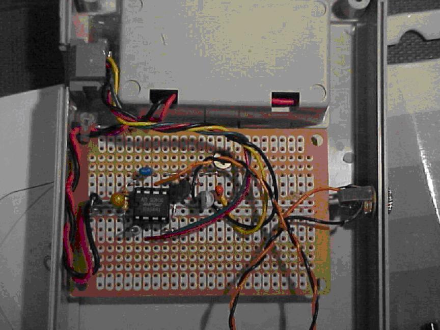
Construction notes for the strain gauge amplifier.
1. The modular jack is a Mouser P/N 154-UL623K4. Leads are Red = in-, Green = in+, Yellow = 5volts, Black = ground.

No comments:
Post a Comment